DREAM HowTo: The Dovetail Puzzle Box
This tutorial shows how to make a simple puzzle box with a clever solution. Check out the video below for a description. Links to all materials and resources are provided below.
|
Materials/Resources Used |
|
|
|
OVERVIEW
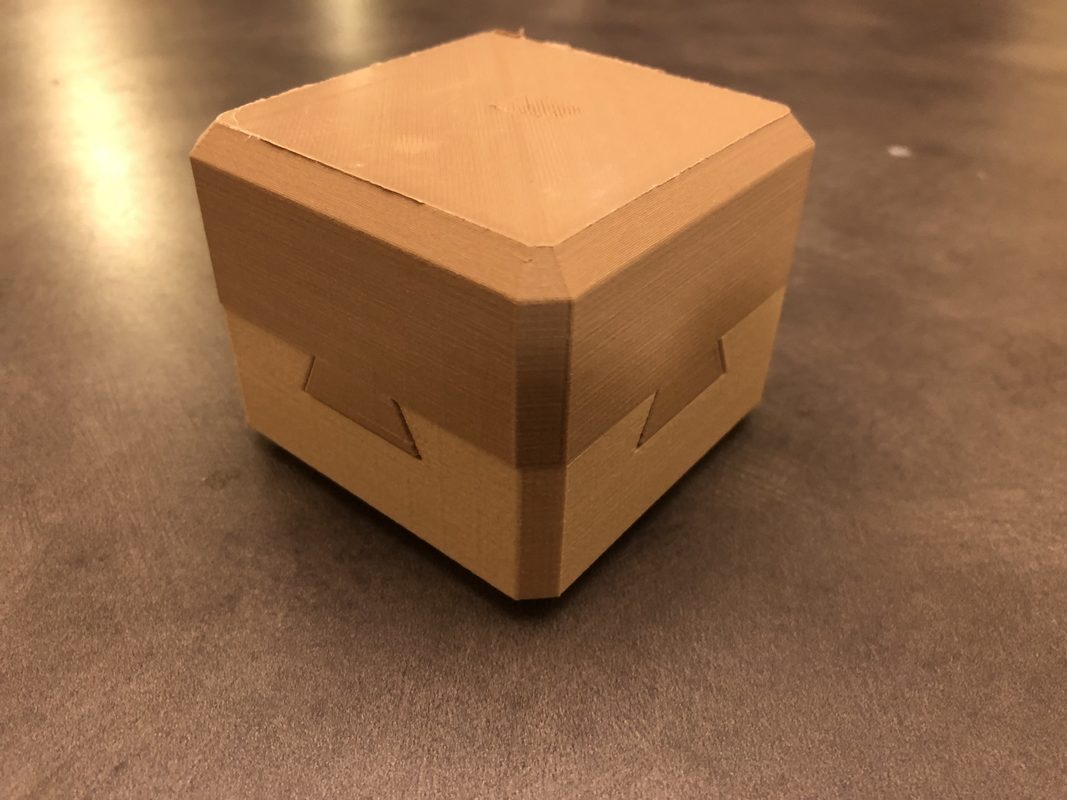
This is a simple puzzle box I designed a year ago as a gift for a friend. The design makes it seem as if there are four intersecting dovetail joints, which would make the box impossible to open. And indeed, when you try to slide it open, it remains shut. One quick tap is all it takes, though—a marble releases from a magnet and is moved to the side, allowing the box to slide open. I've loved puzzle boxes ever since my grandma brought me one back from the Czech Republic when I was young, and now I enjoy making my own. I wanted to explain this process in such a way that would be accessible to nearly anyone, including someone who has little to know experience with any of the resources used here. I tried to explain this project the way I would have wanted someone to teach it to me. And everyone needs a little puzzle box to keep their secrets in, right?
To learn how to make the 3D model on your own in SketchUp, follow the steps below. If you would prefer to just download the STL files for 3D printing, click this download link and continue to the next step in this project.
PART 1:
Making the Model in SketchUp
Step 1: Creating Basic Shapes
When you first open SketchUp, you can delete the little figure of the man. We won't need him. Before we start making things, let's talk about one of the most useful tools: the Orbit tool. To get to this, you can click on the tool with the red and green arrows in the top menu, or just hit the "O" key on your keyboard. This tool lets you rotate around your model to view it from different angles. You can also use the "Pan" tool, which is the one that looks like a hand (or press "H" on your keyboard). This lets you move your view side to side.
And before we get too much further, here's a friendly reminder to save your work often! Like most other programs, SketchUp does occasionally crash.
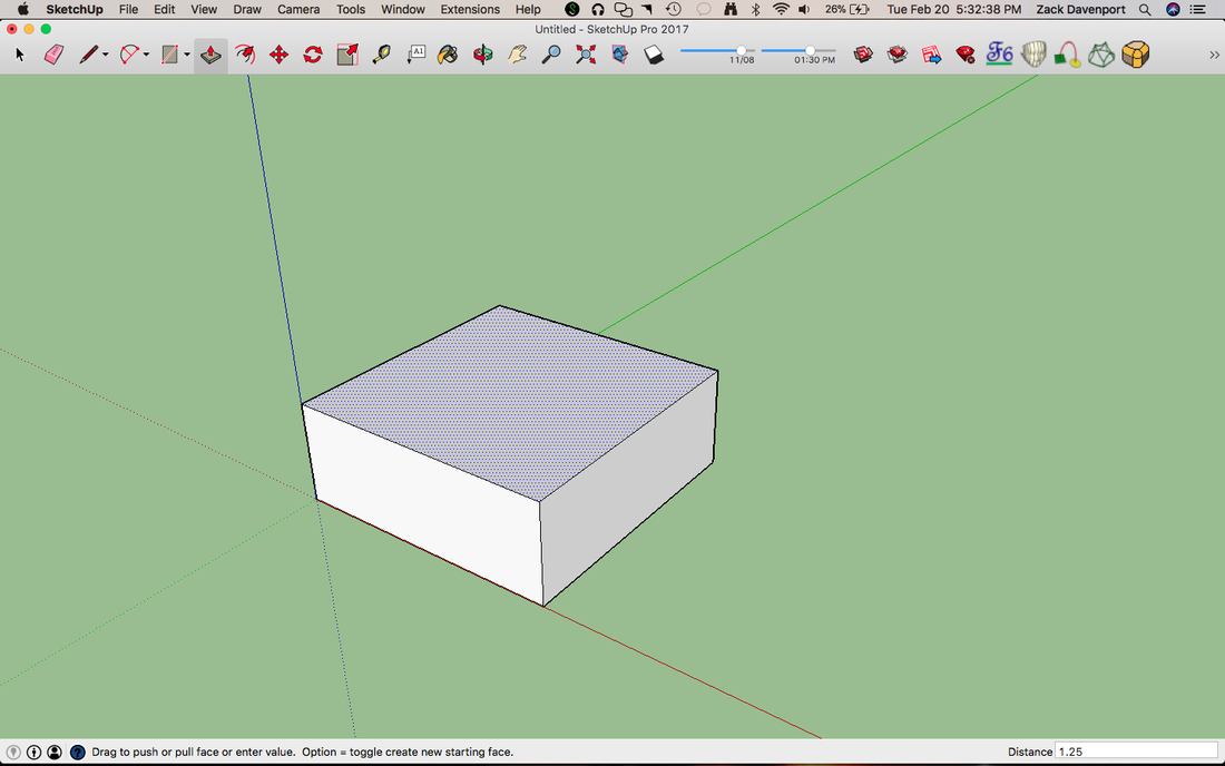
Now, let's make some shapes. Using the rectangle tool (keyboard shortcut: R), draw a 3" × 3" square starting at the origin. You can do this by clicking on the origin with the tool selected and then typing "3,3" and pressing enter. SketchUp automatically assumes all entered measurements are in inches. You should see the "3,3" show up in the text box labeled "Distance" in the bottom right of the screen.
Next, use the Push-Pull tool (P) extrude the flat square into a box. Click on the square with the tool selected and then type "1.25" and press enter, as shown in the above picture.
And before we get too much further, here's a friendly reminder to save your work often! Like most other programs, SketchUp does occasionally crash.
Now, let's make some shapes. Using the rectangle tool (keyboard shortcut: R), draw a 3" × 3" square starting at the origin. You can do this by clicking on the origin with the tool selected and then typing "3,3" and pressing enter. SketchUp automatically assumes all entered measurements are in inches. You should see the "3,3" show up in the text box labeled "Distance" in the bottom right of the screen.
Next, use the Push-Pull tool (P) extrude the flat square into a box. Click on the square with the tool selected and then type "1.25" and press enter, as shown in the above picture.
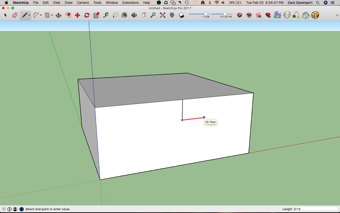
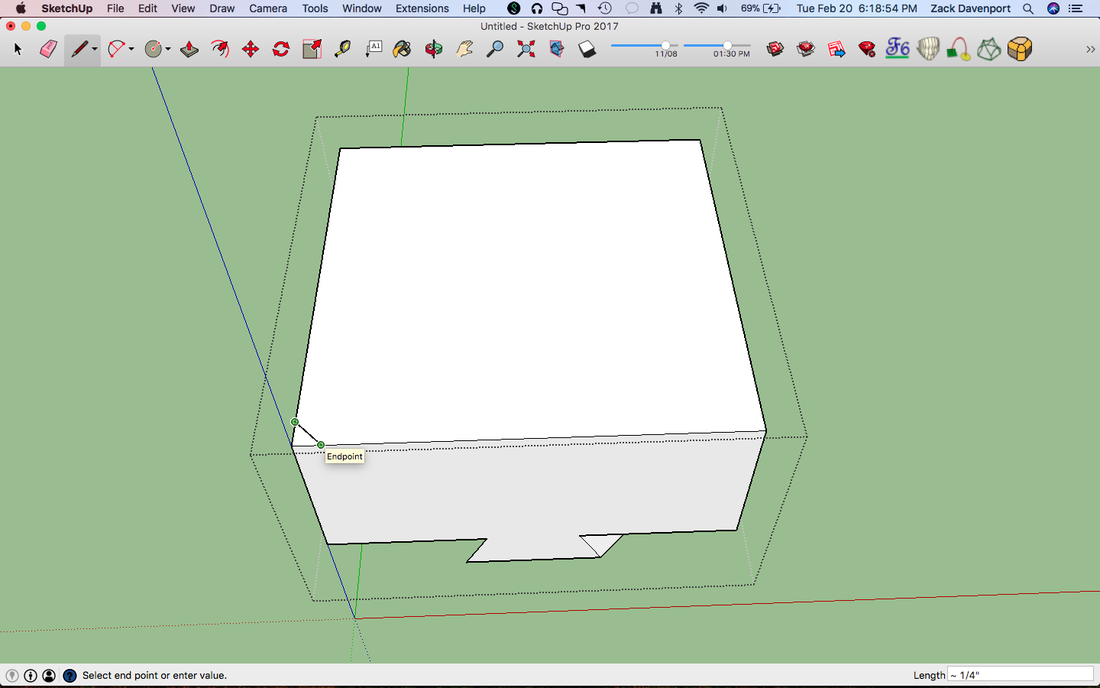
Hover your mouse over one of the top edges of the box, roughly in the middle of the line. When you are in its center, a small blue circle should appear. Draw a line downward that is ⅜" long (type "3/8" and press enter) using the Line tool (L). Lines oriented vertically should appear blue as you draw them. Then draw a line to the right (it should appear either red or green, depending on which face you started on) that is 9/16" long, as shown in the above photo.
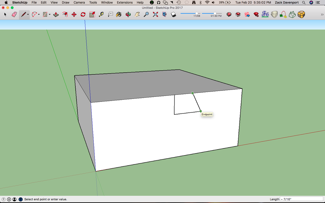
The idea here is that we're forming a trapezoid, and we're making the first half of it right now. Along the top edge from the point where you started, draw a line to the right that is ⅜" long. Connect this endpoint to the lower line, as shown in the image above. We now have half of our trapezoid.
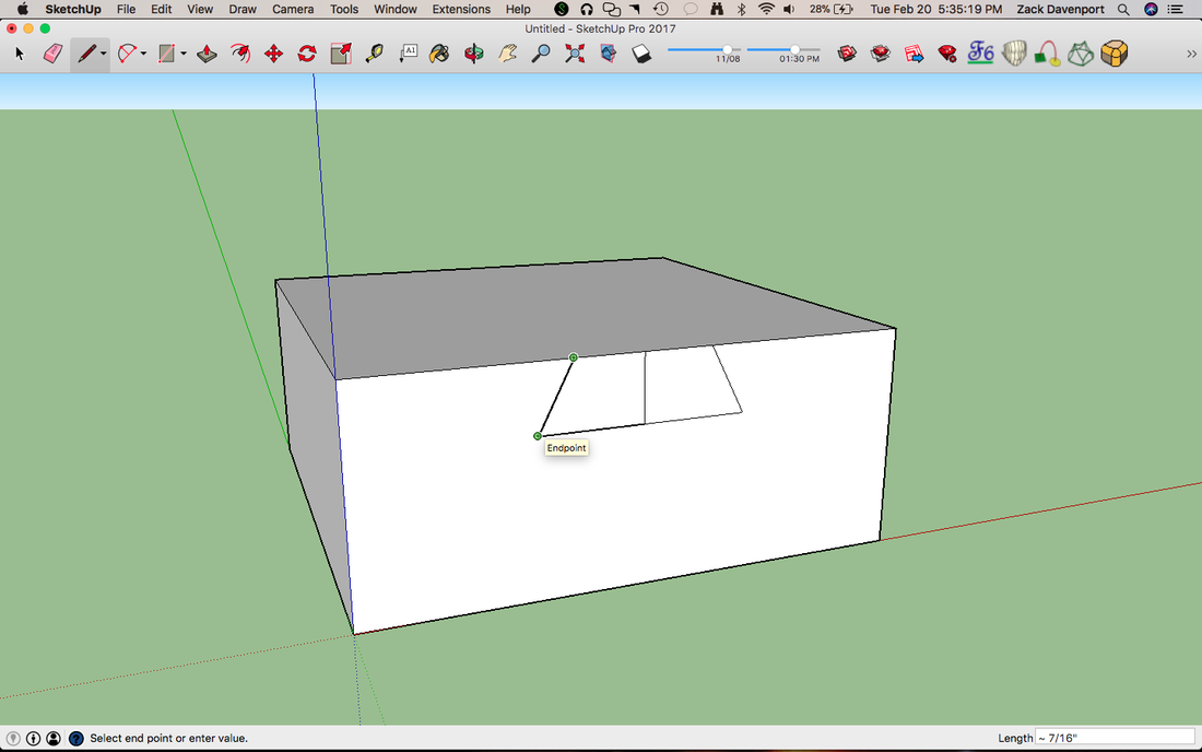
Use the same process above to draw the other half of the trapezoid to the left, as shown in the above picture. When you are done, delete the vertical center line using the select tool (press the space bar) and by hitting "delete."
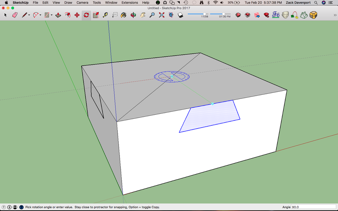
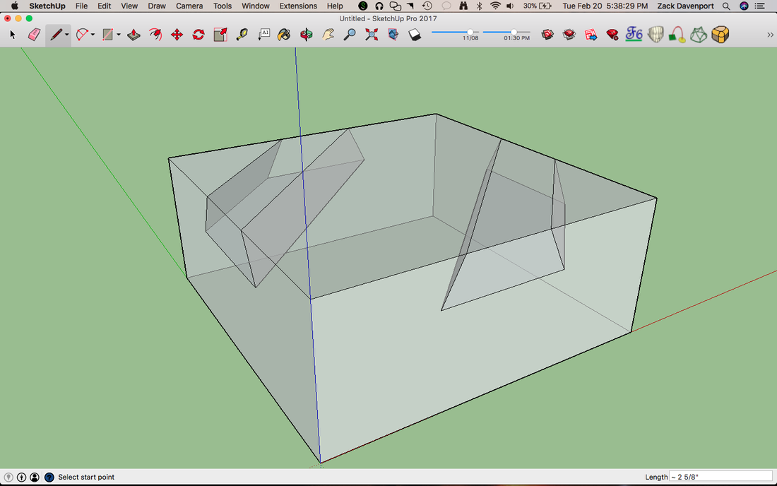
Now, we want to place one of these trapezoids on all four sides of our box. You could draw them again by hand, but there's a faster way - the copy-rotate. Draw a line on the top face from one corner to another, as shown in the above picture. Select your trapezoid and its edges by double clicking with the select tool on the trapezoid. Then, select the Rotate tool (Q). Place your cursor in the center of this line (look for the blue dot!) and click, then click again on the trapezoid. Then, press the Ctrl key (if you're using a Mac, press the "option" key) and a small black plus sign should appear. This indicates you are copy-rotating. Type 90 for the angle and press enter, then type "x3". This tells it that you want three more copies (four trapezoids total), each rotated 90° from the previous one. You can sort of see how this works in the above picture.
The completed copy-rotate should look like this. NOTE: I have X-ray view turned on, which will be very useful for the next step. To turn this on, go to View->Face Style->X-ray, or set a keyboard shortcut for it.
Step 2: Creating the Grooves
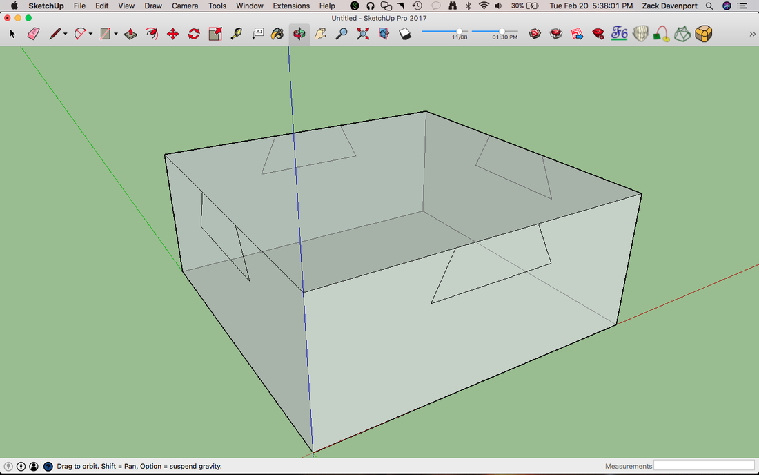
Now, with X-ray turned on, we'll draw lines from one trapezoid across to the other, as shown in the above picture. This is creating the tracks our box will slide along.
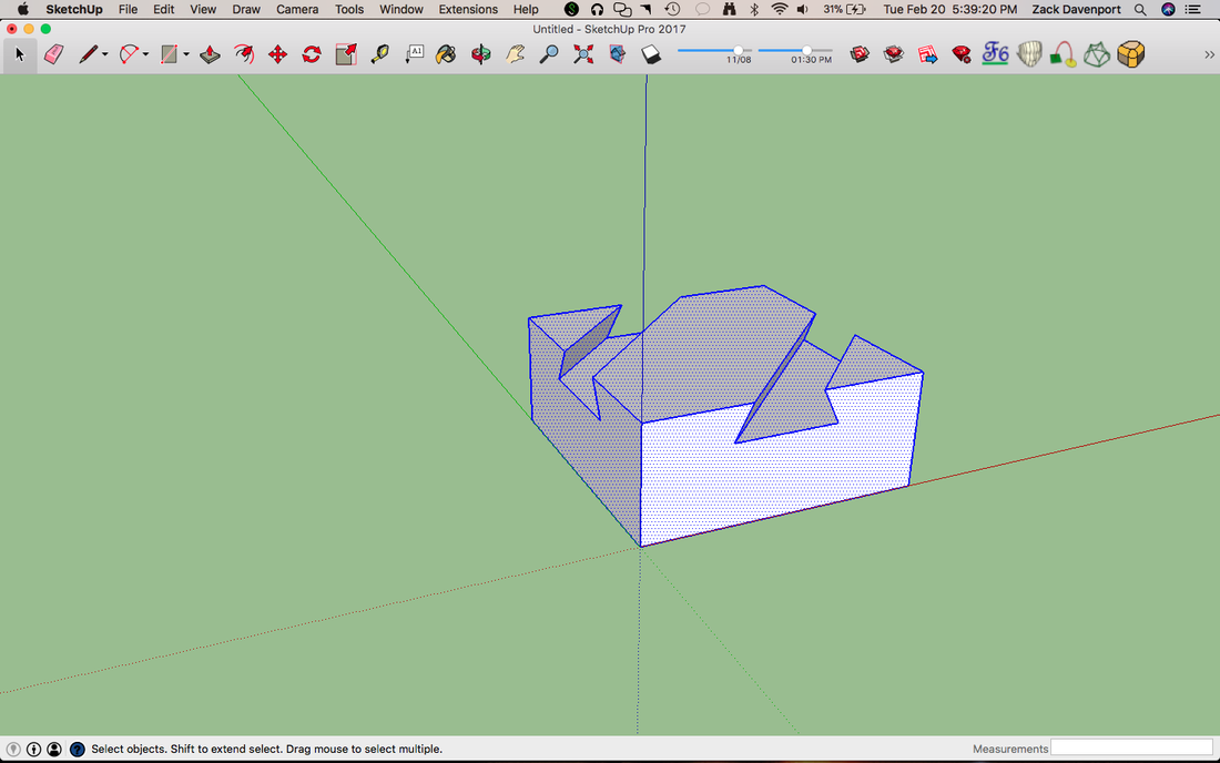
Next, delete the lines that define the tops of the trapezoid. This will open up the channels. If the faces appear blue instead of white, you can right-click on them with the select tool and choose "Reverse Faces". Now, let's make this part into a group. Select everything using Ctrl+A or by triple-clicking on the model. Everything should turn blue, like in the above picture. Now, make this into a group by right-clicking and selecting "Group" or using Ctrl+G. Blue lines should now form a box around all of the outer edges.
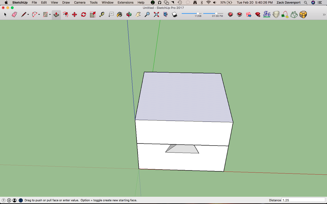
Next, draw a square across the top face, just like we did when we were starting. It should be the same size as the below box (3" × 3"). Use the Push-Pull tool to extrude it up 1.25" as shown in the above image.
Now, trace along one of the trapezoid shapes with the Line tool, going from one vertex to the next. After you trace along all edges of the trapezoid, it should fill in as a solid face as shown above.
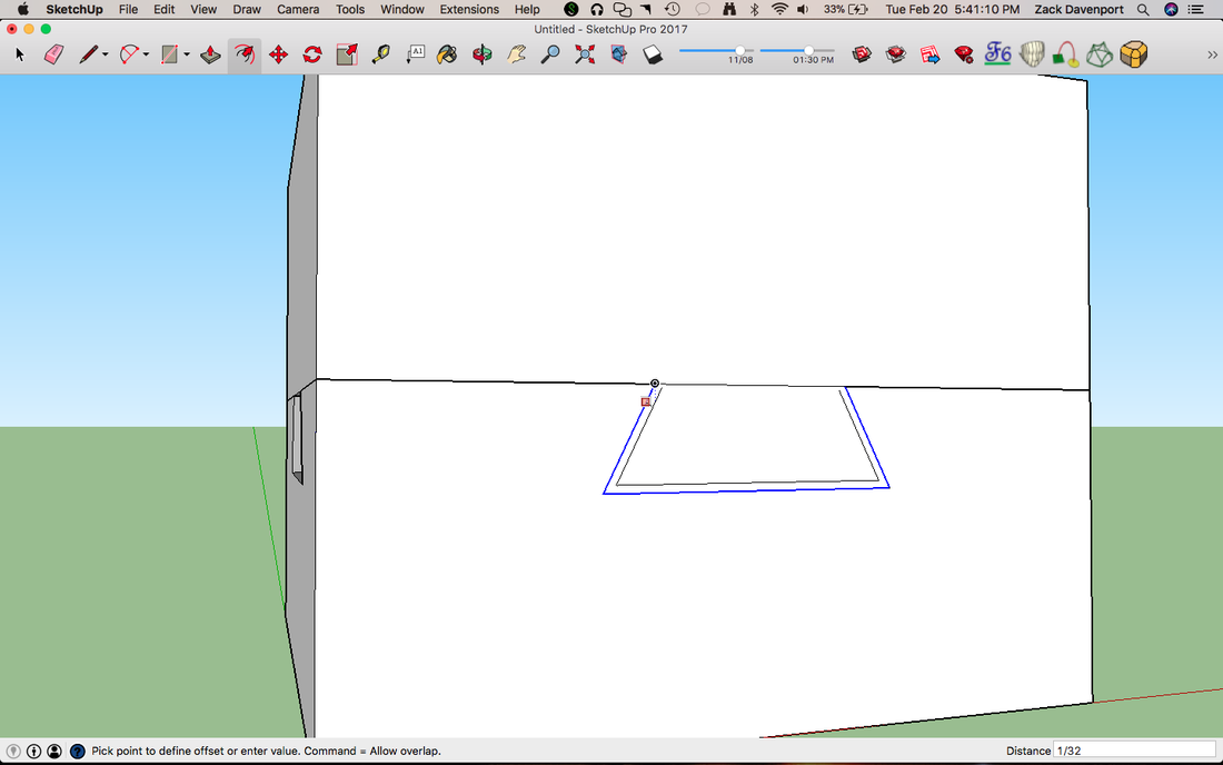
Select the three sides of the trapezoid (all sides but the top one) using the select tool. You can select multiple lines at the same time like this by holding down "shift" while clicking on the lines. Now, select the Offset tool (F) and click on one of the highlighted lines. If you move your mouse into the trapezoid, you should see a smaller trapezoid forming. Type "1/32" for the distance we want to offset. This offset is so the two halves of our box have some space to slide, so they won't get stuck. This is called "tolerancing."
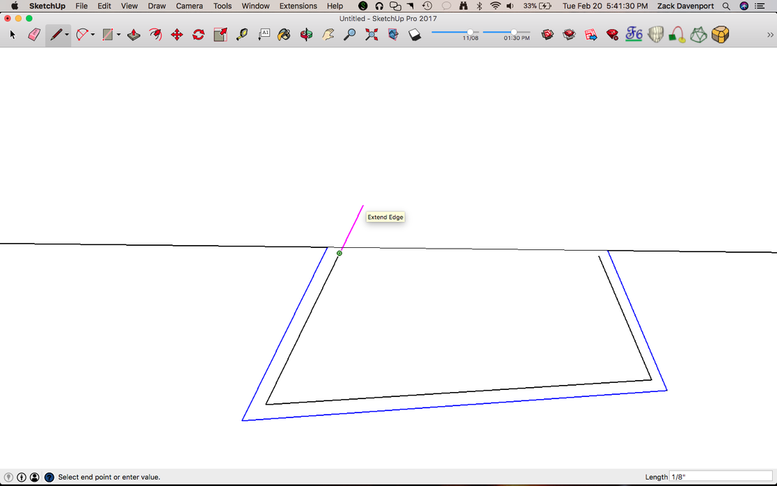
You'll notice that the new smaller trapezoid's sides don't fully extend up to the top line. We'll have to do this manually. Use the pencil tool and continue the lines upward toward the top. They should turn pink, indicating that you are extending the edge. Do this for both sides of the trapezoid and delete any extra line segments that extend past the top line.
Next, delete the white space between the larger trapezoid and the smaller trapezoid so there is a hole between the two of them. Now, we'll copy-rotate the new smaller trapezoid onto the other sides using the same process we did for the first one, as shown in the above picture.
Now, we want to group the top box. Do this using the same process as before. We can "enter" this group so we can mess around with its geometry by double-clicking it with the select tool. It should look something like the picture above. For the next step, we'll want to make it so where the top box is the only visible group. To do this, go to View->Component Edit->Hide Rest of Model, or set a keyboard shortcut for this as it is a very useful feature.
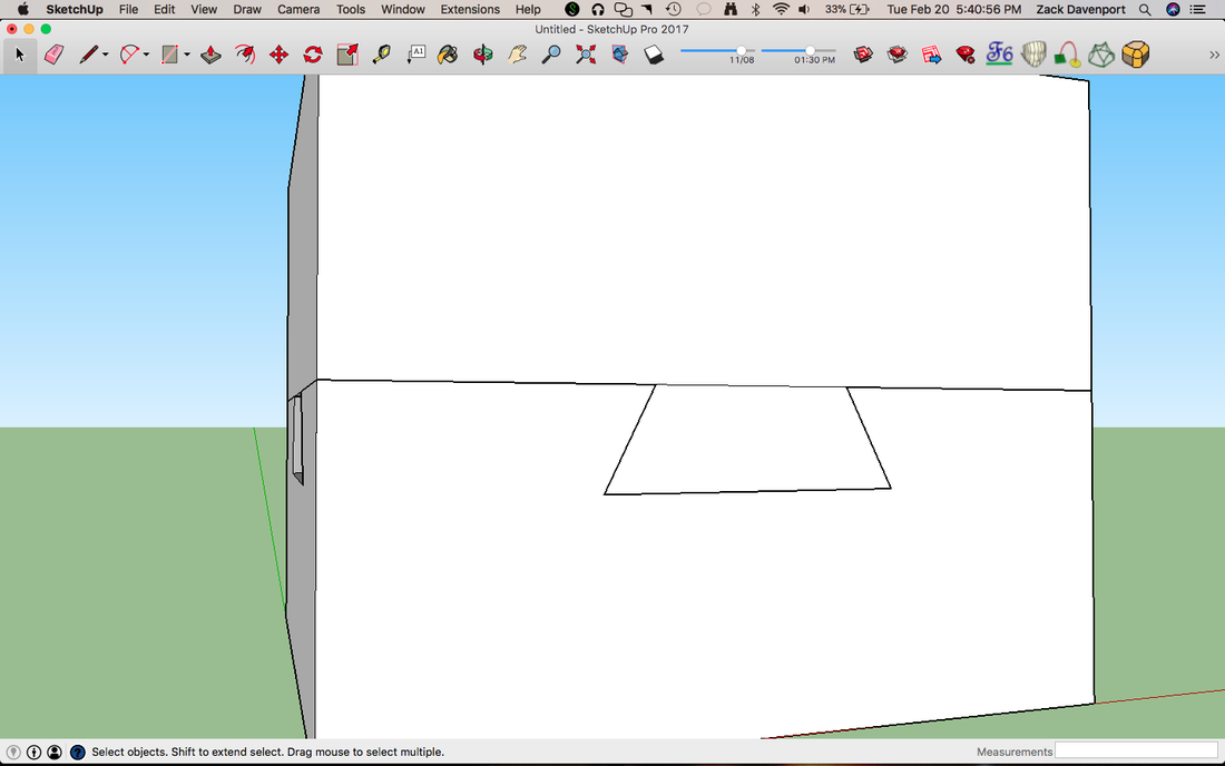
Now that we have just the top box visible, draw lines from one trapezoid across to the other as shown above, just like we did earlier on. There may still be small line segments from where we extended the legs of the trapezoid earlier, so be sure you draw lines from the upper-most endpoints. Now you can delete the lines that separate the trapezoid shapes from the rectangular sides of the box.
Step 3: Creating the Pockets
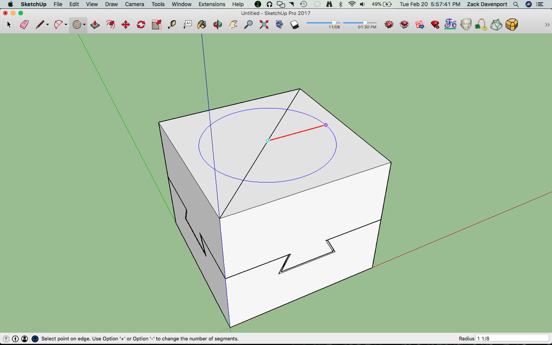
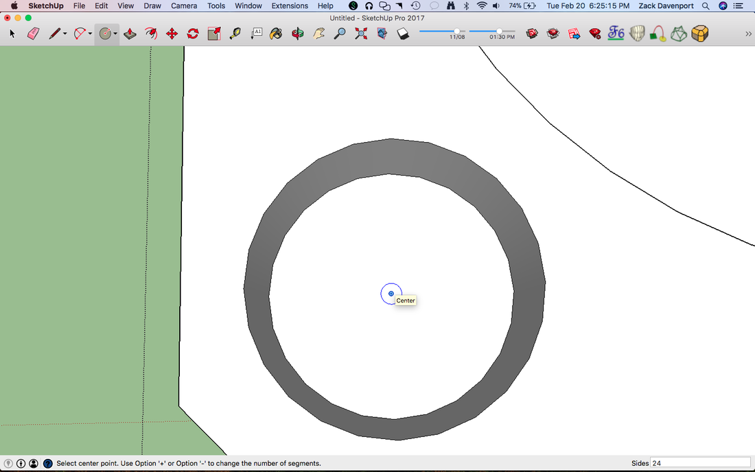
To close out of this group, hit "escape" (this only works when you're in the select tool). Next, we'll make the circular pockets on the inside of our box. To do this, draw a diagonal line across the top and use the Circle tool (C) to draw a circle from the center of the diagonal line, as shown above. Type in "1 ⅛" to give the circle a radius of 1 ⅛" inches. All circle measurements are entered based on their radius. Be sure to move your mouse along the direction of the red line (or the green line, if you choose). A red line will appear inside the circle when you do this, as shown in the picture above.
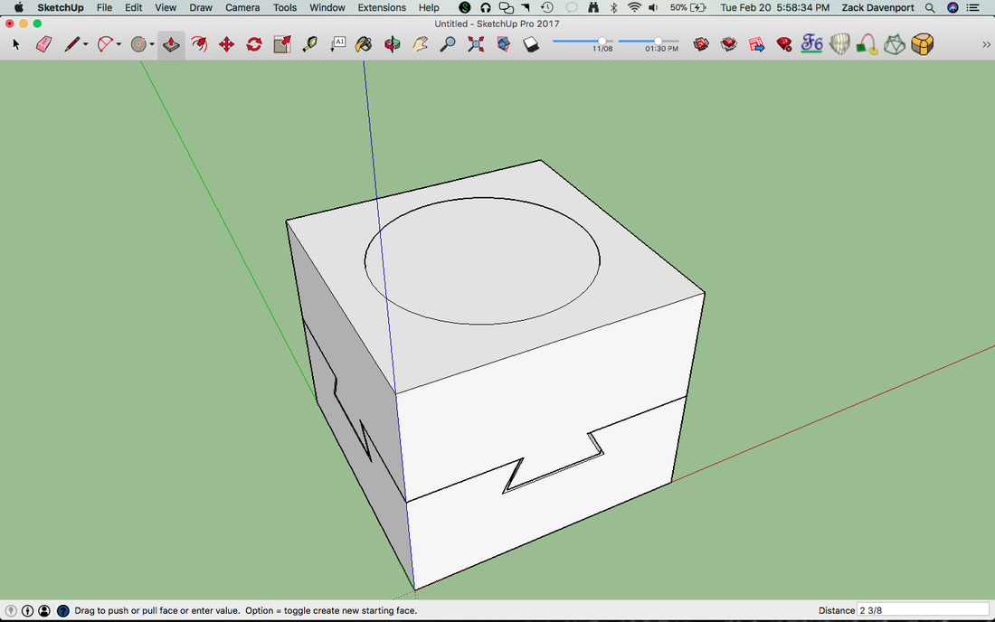
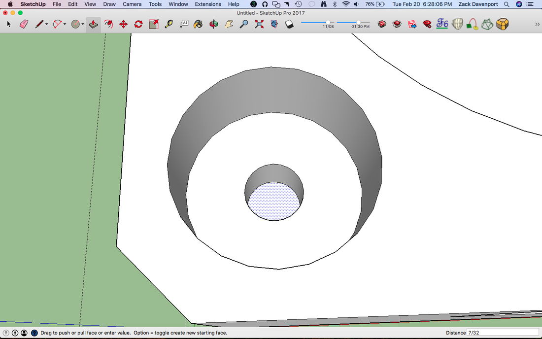
Delete the diagonal line and click on the circle. Use the Push-Pull tool to push the circle into the box and type in "2 ⅜" for the distance, as shown above. It's kind of hard to see what is happening here, so you may find that the X-ray view is more helpful.
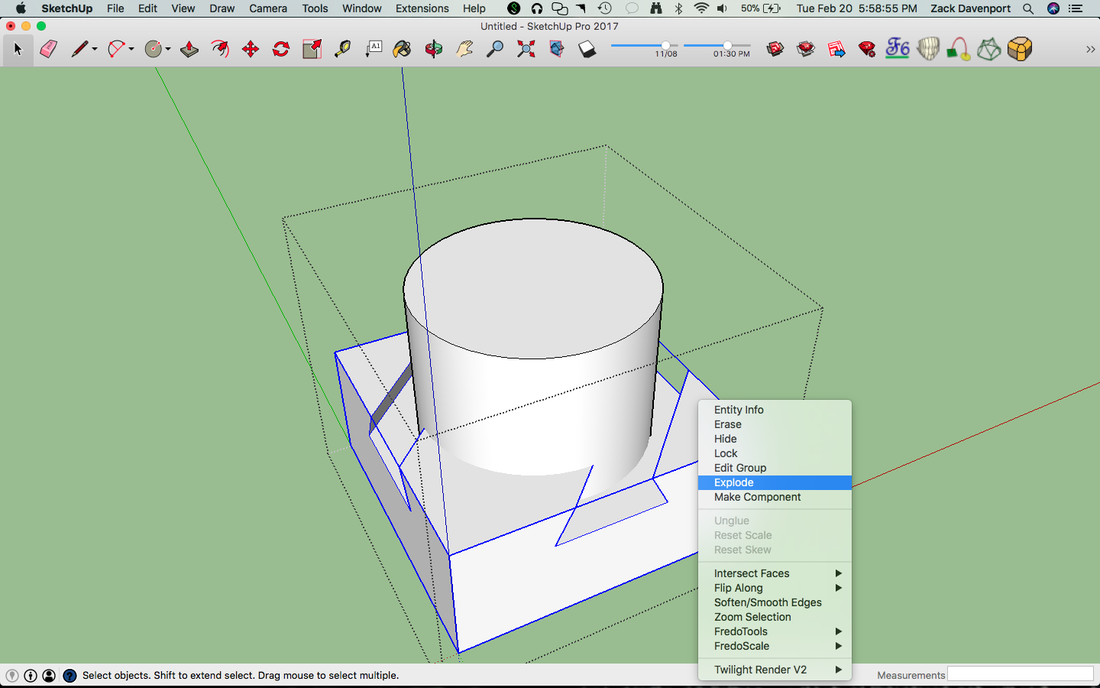
Triple-click on the circle (this will select the circle and all its attached parts, because we just made it into a cylinder by extruding it into the box) and then hold "shift" to select the lower portion of the box as well. Group these together (Ctrl+G) and then enter the group by double-clicking. Right-click on the lower part of the box and click "Explode". This takes the geometry out of grouped form, which we need because we have a group inside of a group.
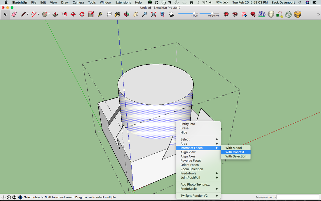
Now, select the side face of the cylinder, right-click, and go the "Intersect Faces" menu as shown above. We want "With Context"; this will find all the places that the selected face intersects with the geometry in our current group (the context).
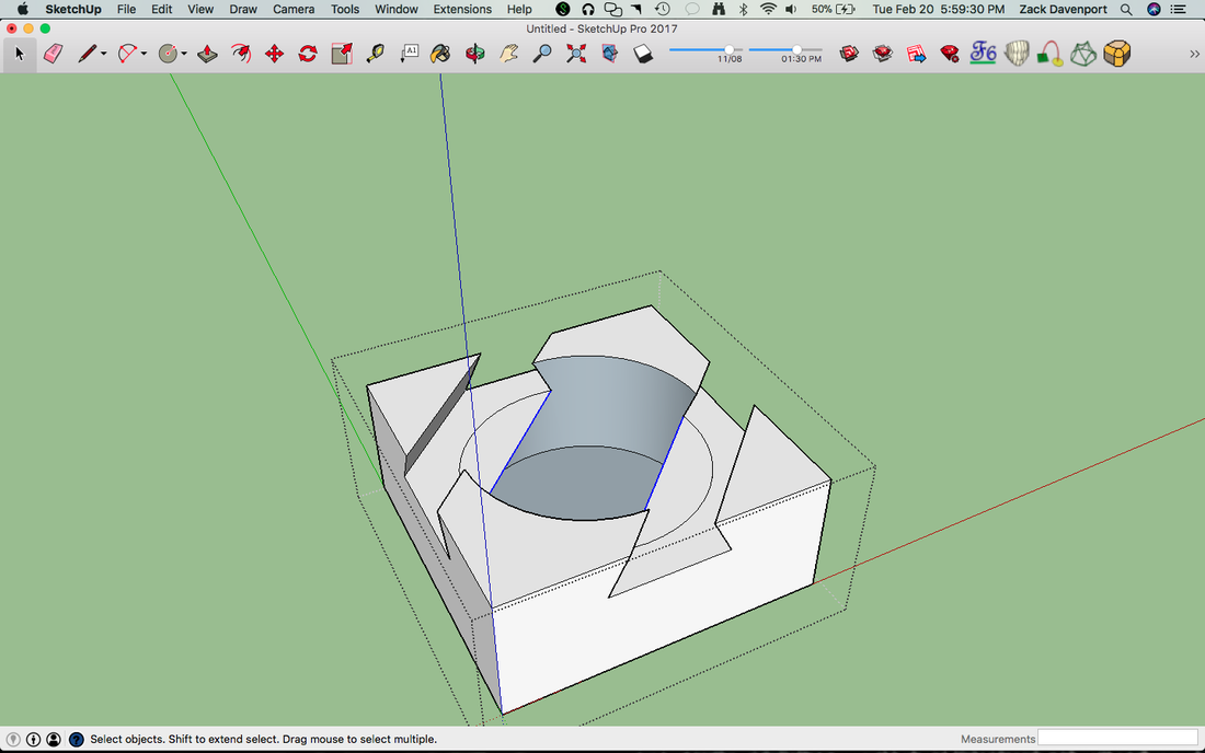
Now, delete the side face and the top circle. You will also need to delete some of the lines running between the trapezoids to open up the circle, like the ones selected above. If the inside pocket is blue, select the blue faces, right-click, and select "Reverse Faces" like we did earlier. Our bottom pocket is now mostly done! Let's do the same for the top half of our box.
Draw a circle of the same size using the same process from earlier, but this time on the bottom size of the box. Extrude it 2 ⅜" into the box, just like we did earlier.
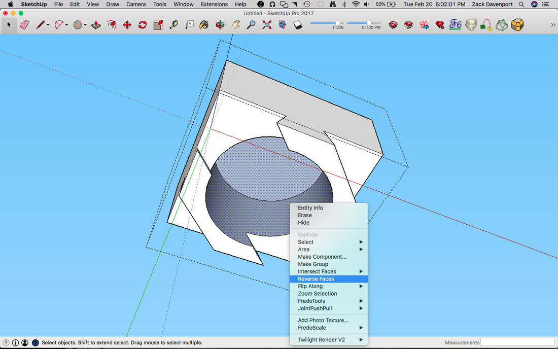
Just like before, we'll group the circle and the cylinder attached to it with the top half of the box. Go into the group, explode the top half of the box, and intersect the side of the cylinder with the context like in the previous steps. Reverse the faces, as shown above, if needed.
Step 4: Making the Chamfer (Sloping Edges)
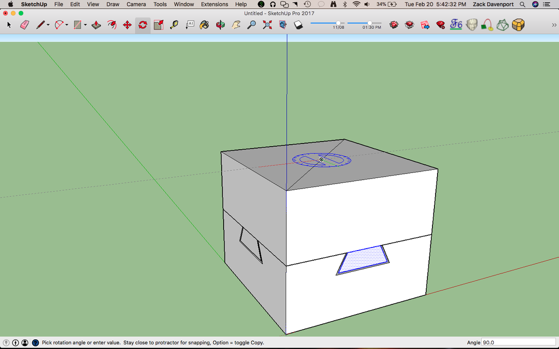
First, open up the top group by double-clicking. We'll draw a small triangle in the corner. Make each side along the edges 3/16" and then connect them to form a triangle as shown above. Next, we'll copy-rotate them using the same process as before to get one in each corner.
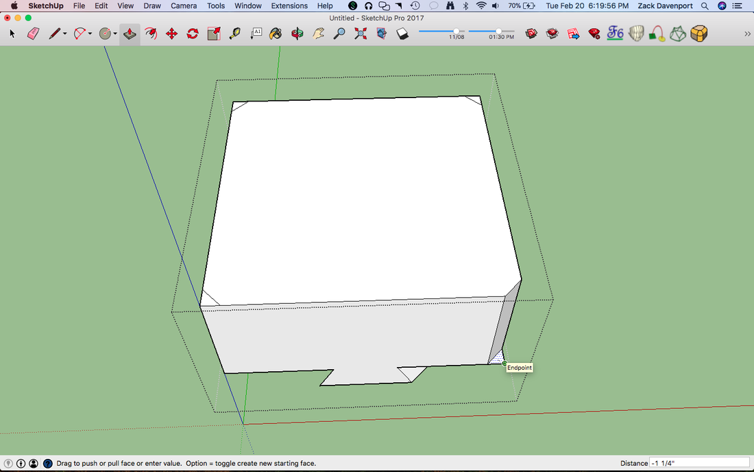
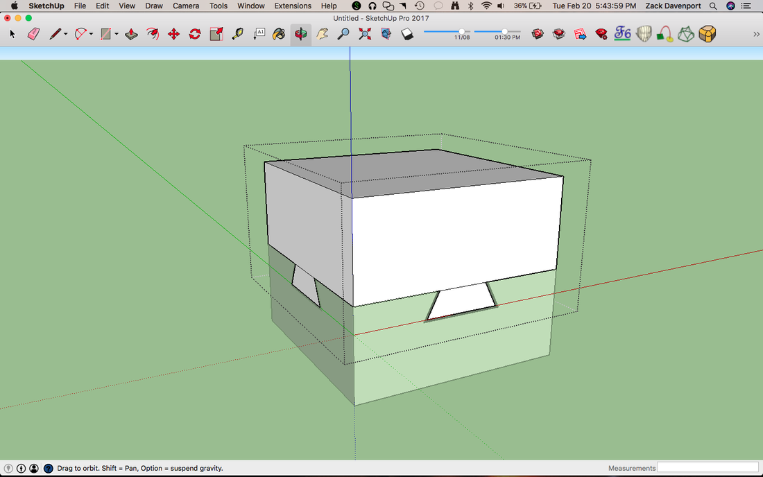
Use the Push-Pull tool to push each of the corner triangles all the way down. Once you push them to the point where you only see a single 2D-face, click and the face should go away entirely. Do this for the other three triangles.
Now, we want to draw the same triangle but on one of the edges of the box. You can sort of see this happening in the above picture: start on the upper edge and draw a line down the side of the box, and then draw another one connecting to it that goes across the top of the box. Make each of these lines 3/16" long like the last triangles. Next, draw a line that goes through the inside of the box to connect these two lines into a triangle. The X-ray view might be useful here.
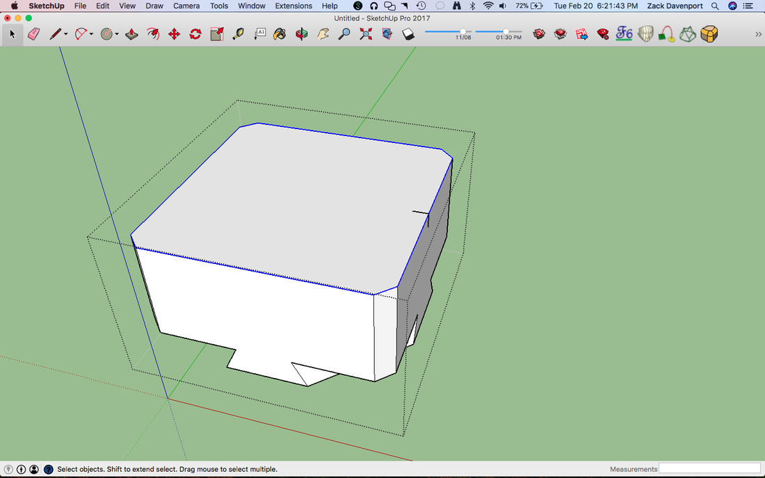
Now that we have that triangle created, we're going to use a fancy tool called the Follow Me tool. Go to View->Tool Palettes->Large Tool Set and then find the tool about halfway down on the right side that looks like a curving arrow, but don't click on it just yet. This tool takes a shape and makes it extrude that shape along a path. First, we have to select the path. We want the outside edges of the top face of our box, the ones highlighted in blue in the above picture. To quickly select these, double-click on the top face of the box with the select tool to select the face and the edges. Then, hold down "shift" and deselect the face. Just the edges should remain now. This will be our path.
Now that we have that triangle created, we're going to use a fancy tool called the Follow Me tool. Go to View->Tool Palettes->Large Tool Set and then find the tool about halfway down on the right side that looks like a curving arrow, but don't click on it just yet. This tool takes a shape and makes it extrude that shape along a path. First, we have to select the path. We want the outside edges of the top face of our box, the ones highlighted in blue in the above picture. To quickly select these, double-click on the top face of the box with the select tool to select the face and the edges. Then, hold down "shift" and deselect the face. Just the edges should remain now. This will be our path.
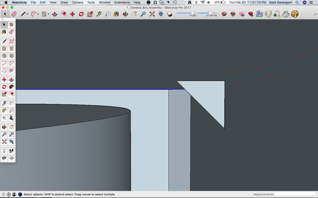
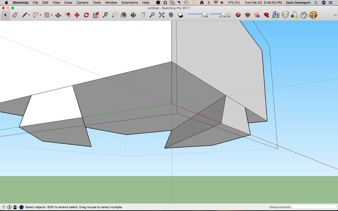
Now, we'll do something a bit interesting. Use the Orbit tool to move inside the top of the box, right where our little triangle is. You'll know it's the inside because everything will look kind of bluish, as shown in the picture above. We should still have the blue lines selected from the previous step, as shown above. Now that we can see the triangle, click on the Follow Me tool and then just click on our little triangle, then watch the magic happen.
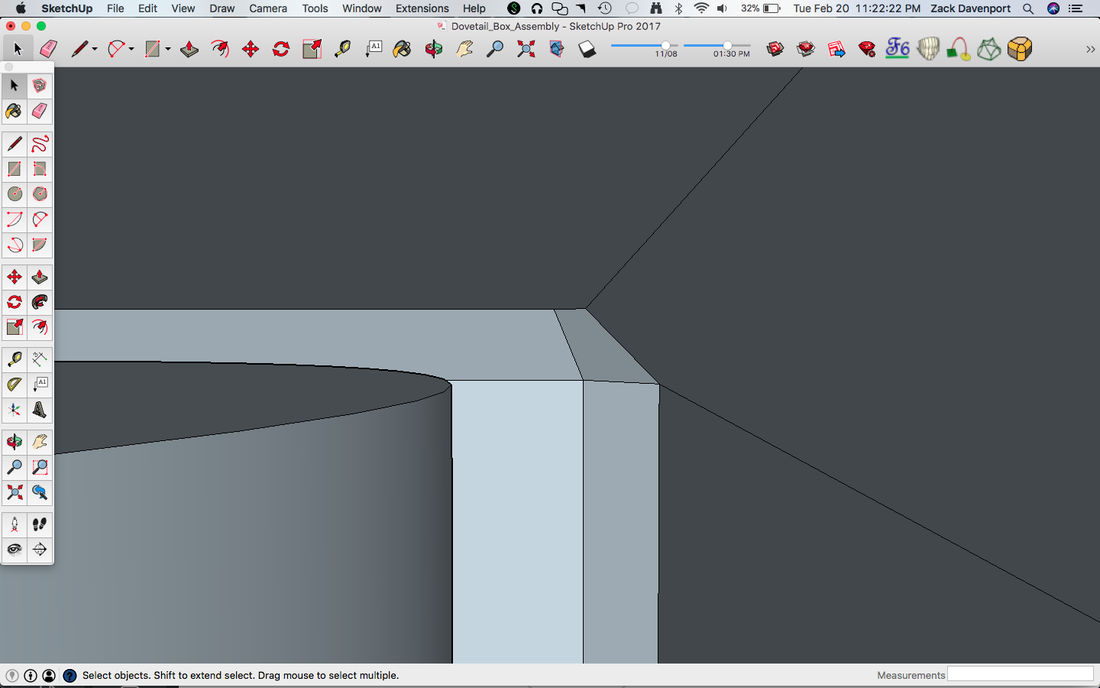
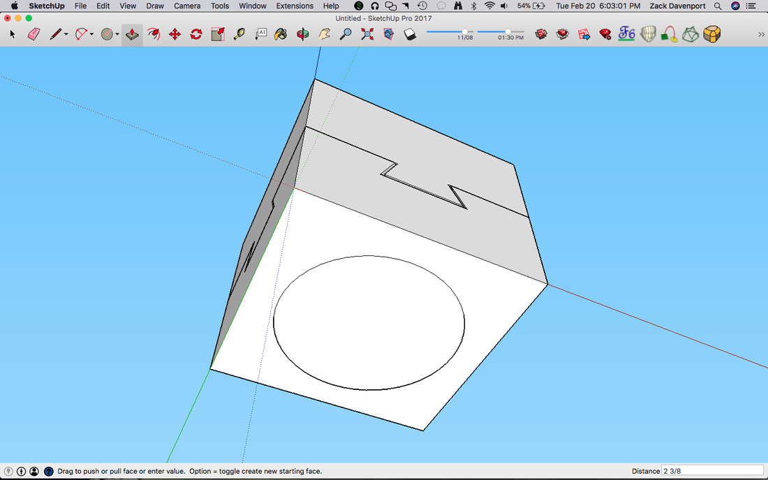
The inside of the box should now look like the picture above.
Now, we want to do the exact same process for the lower part of the box. Make the corner triangle and copy-rotate it to the other corners and Push-Pull them away. Make the interior triangle along the bottom edge just as before, and then select the outside edges for the Follow Me tool's path and let it do its magic. The final result should look something like the above image.
Step 5: Making the Pockets for the Ball Bearing
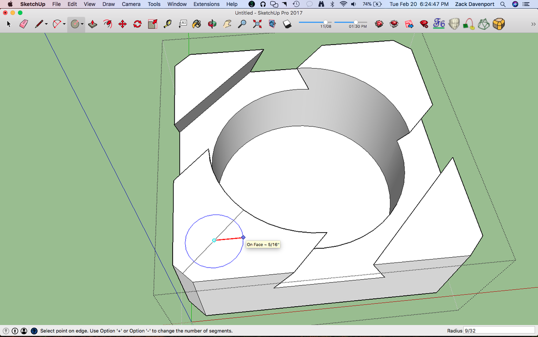
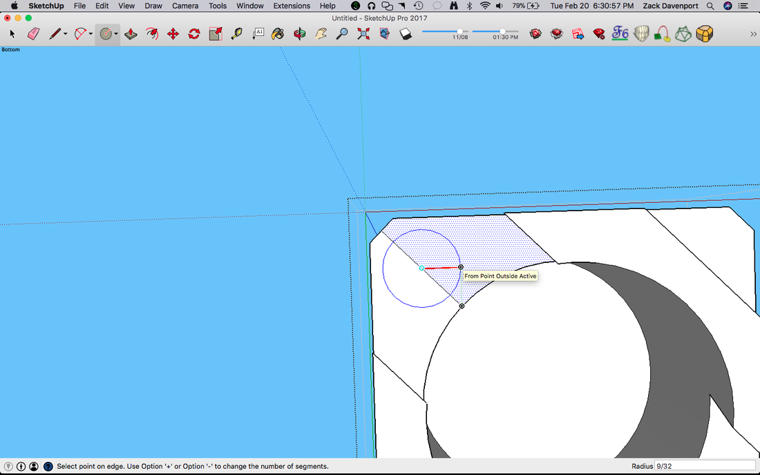
Now, let's open up the lower part of the box. In the bottom left corner, draw a line from the center of the chamfered edge to the edge of the pocket circle. Circles in SketchUp are just made up of lots of small lines, and so we can draw our line straight across to one of the points on the pocket circle, as shown above. Now, we'll draw a circle from the midpoint of this line (make sure to move your mouse along the direction of the red line, as shown). Make the radius for this circle 9/32". This will give our ½" ball bearing just enough room to slide around on the inside.
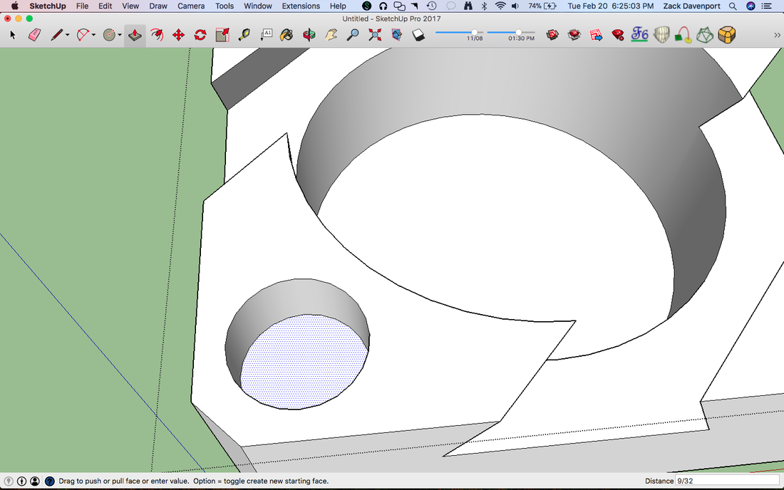
Now, use the Push-Pull tool to push this circle into the box as shown above. The distance should be 9/32". Our ball bearing is ½" in diameter, so a pocket of this depth will allow the marble to rest just below its halfway point in the pocket.
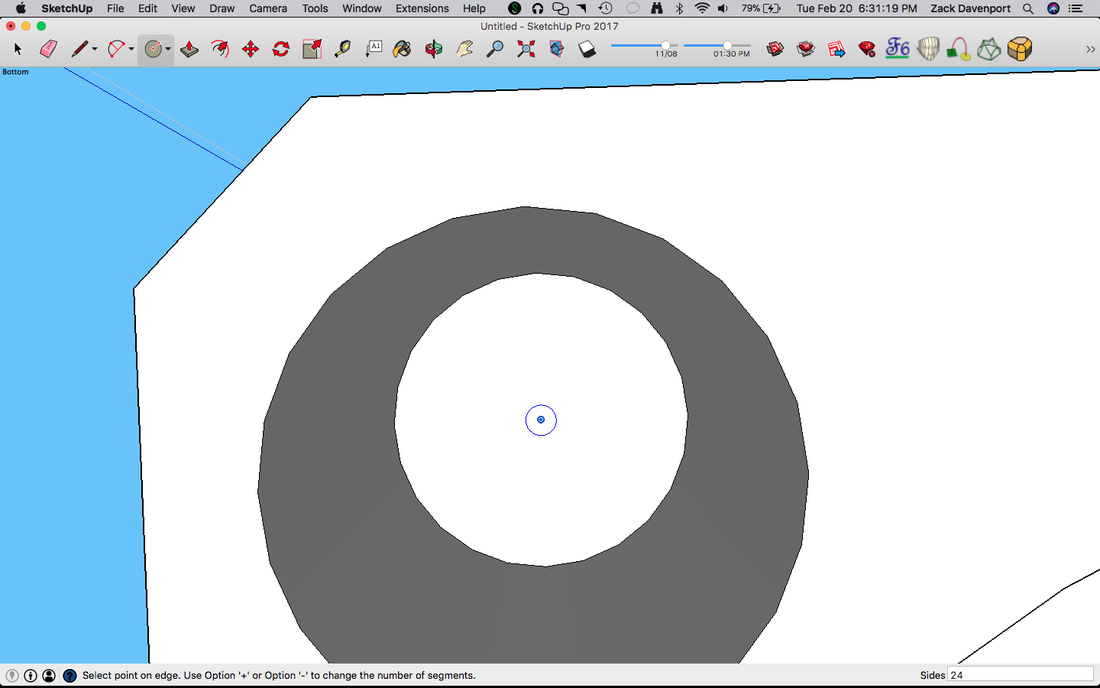
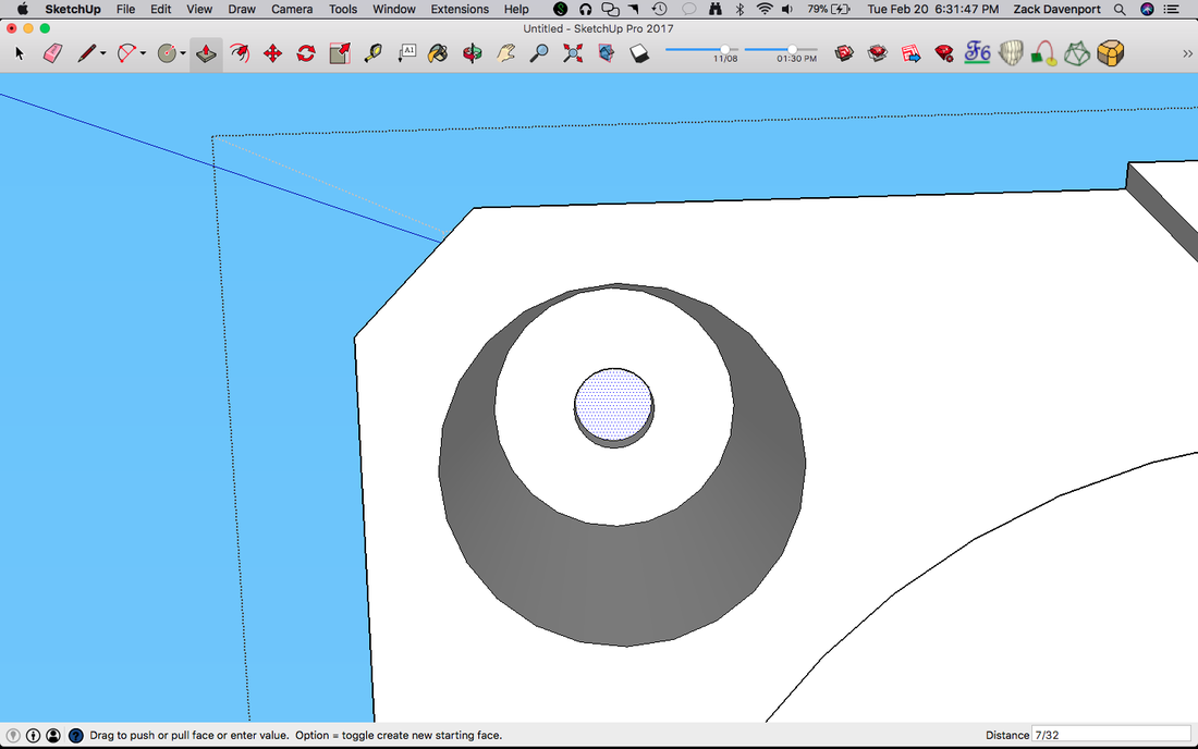
Now we're going to draw another circle centered inside the first circle to make the pockets for the magnets. If SketchUp is feeling nice, you can select the circle tool and bring your mouse over the center of the first circle where it will show a dark blue dot and maybe the word "Center", like in the picture above. If it does not do this, you can always draw a line from one side of the circle to the other (the circle's diameter) and use the midpoint of that line. We'll make our next circle in the center of the first circle and give it a radius of 0.094375". This number is very precise, but it is just the right size for our little magnets.
Now, Push-Pull this circle into the box as shown above. The distance should be 7/32.
Now, we'll do pretty much the same process to create holes in the top half of the box. Open up the top half's group and draw the same sized circle (9/32" radius) just like before. Be sure you make this circle in the same corner as the last one so the pockets line up!
Push-Pull this circle into the top of the box to make a pocket that is 27/32" deep. Next, we'll make the same circle in the center for the magnets.
Just like before, Push-Pull this circle into the top of the box to make a pocket 7/32" deep, as shown above.
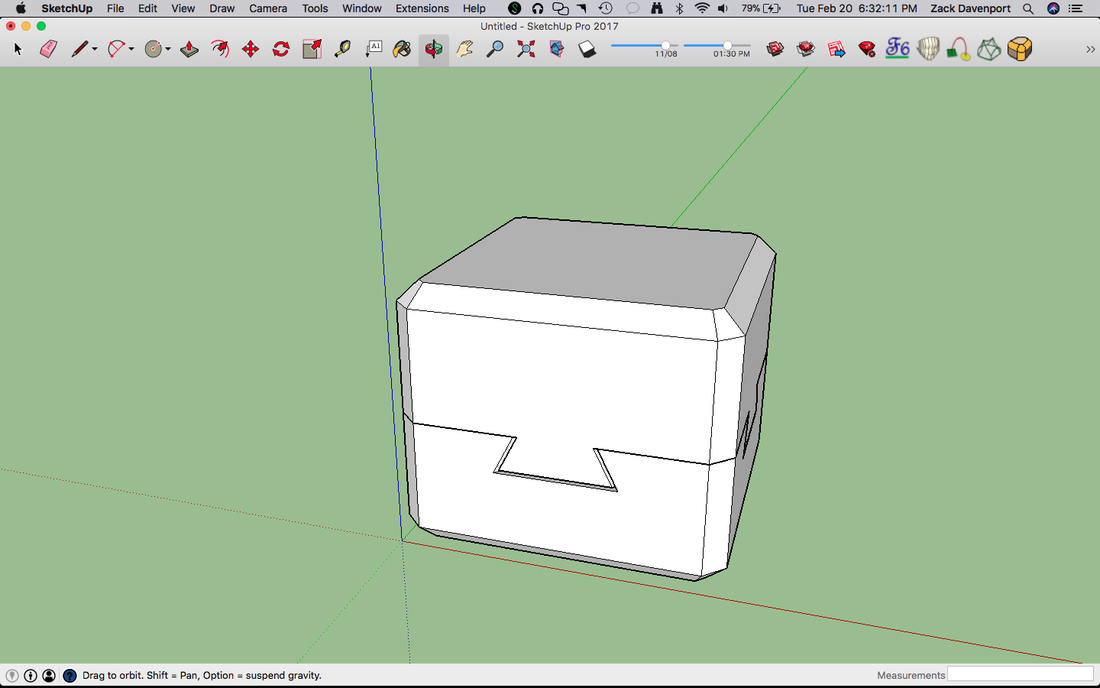
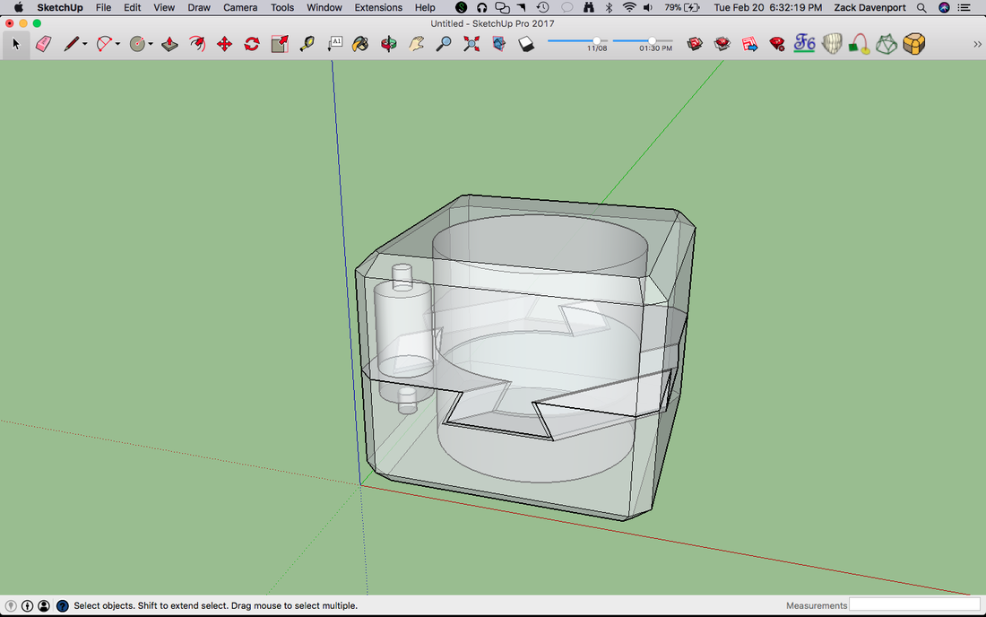
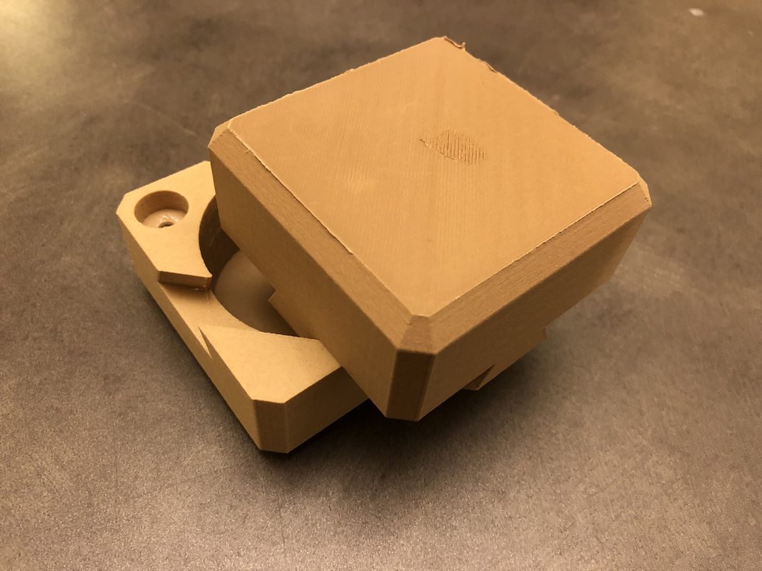
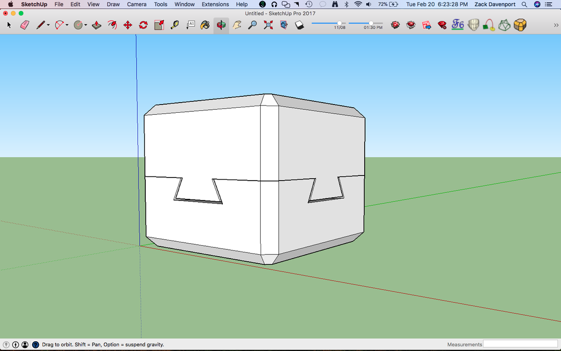
That's it! We've made all the geometry of our box. The pictures above show the final box in its normal view and in its X-ray view. Now we just need to save the pieces so they can be 3D-printed.
Step 6: Saving the Parts
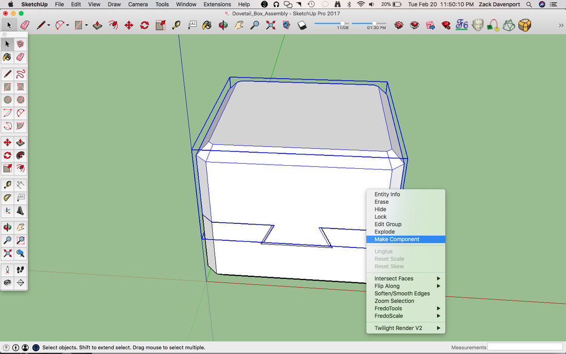
To save the parts individually, we need to change them from groups to components. To do this, right-click and select "Make Component," or use the Group shortcut Ctrl+G again. A component in SketchUp is sort of like a next-level group--when you make copies of it and change one, all the other copies change in exactly the same ways. And, you can save them as individual parts, which is what we're about to do.
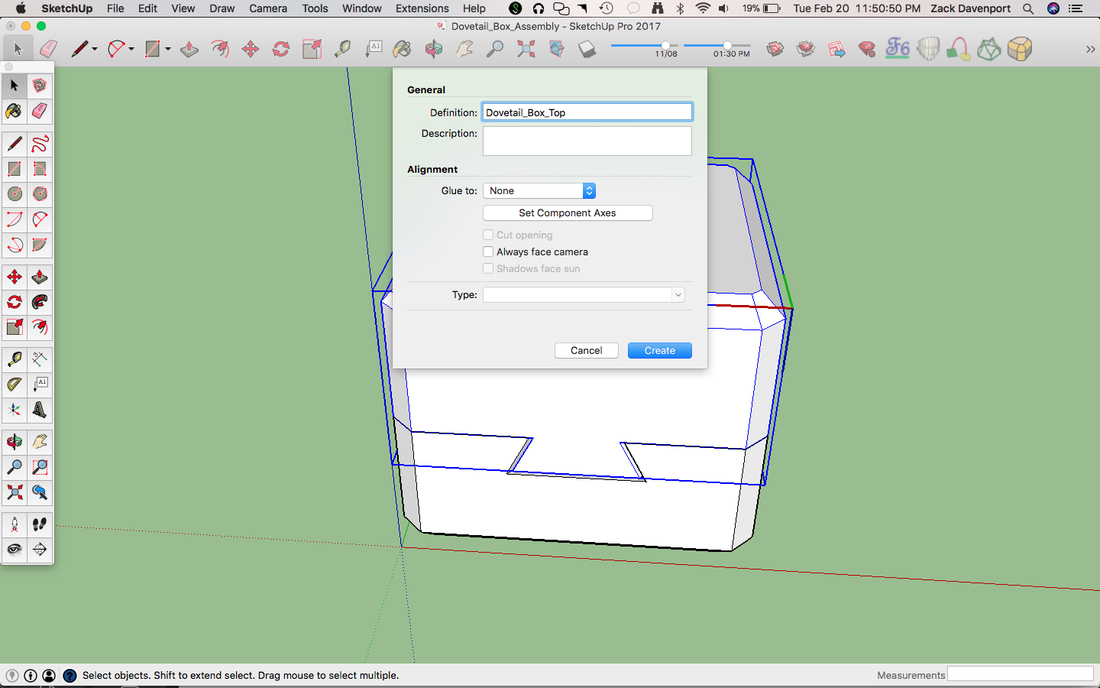
Now, it'll ask us to name our component. Call it something descriptive like "Dovetail_Top_Box" (underscores are not necessary, just a force of habit for me), or "Top" will suffice. Then click "Create."
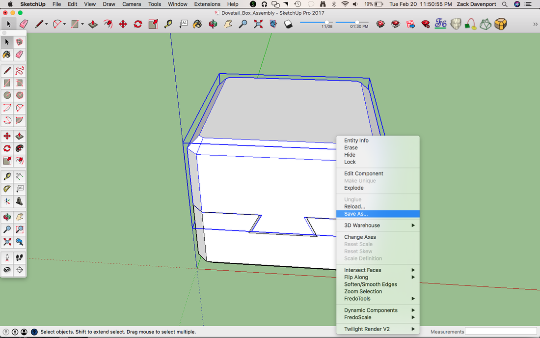
Now, right-click on the component and select "Save As...". This will take you to a standard "save" menu. Save it some place you can find it easily.
Now, do this same process of converting to a group, naming, and saving for the bottom half of the box.
Now, do this same process of converting to a group, naming, and saving for the bottom half of the box.
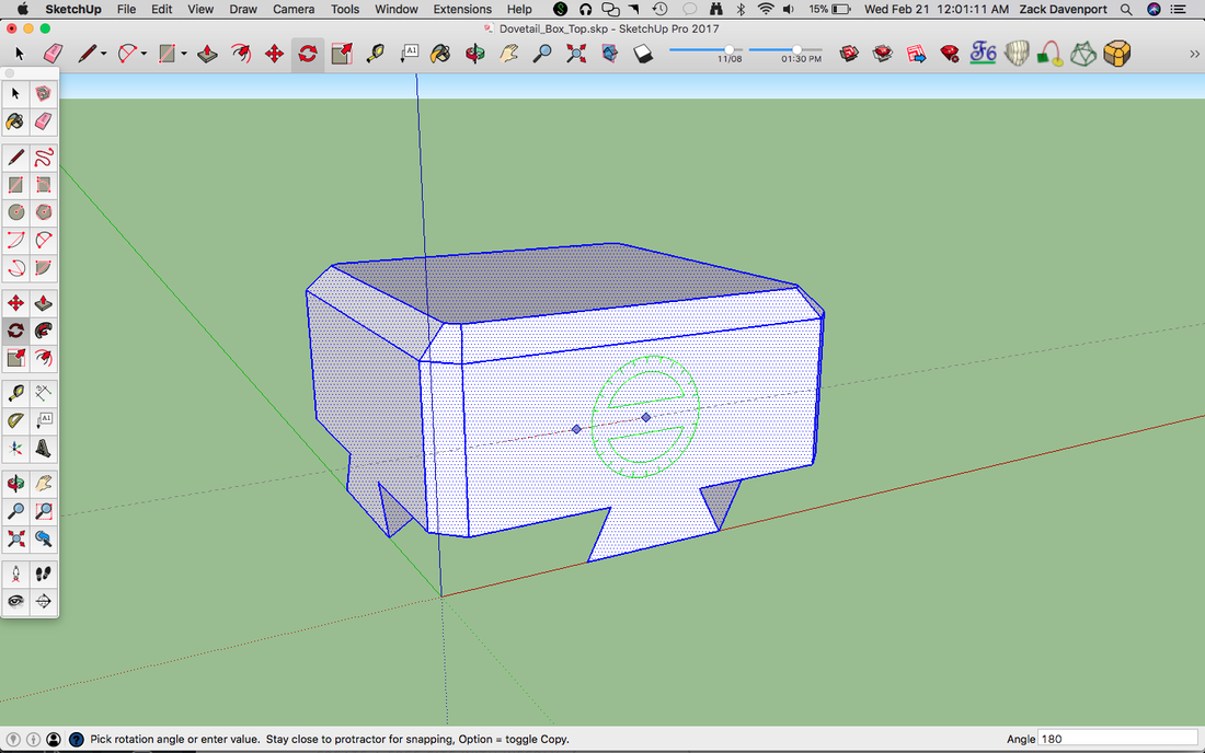
Now, open up the components you saved just like you're opening a normal file. You'll notice that they save in the same position that they were created in. This means the bottom of the box will be flat-side down, but the top of the box will be flat-side up. This is not the best orientation for 3D-printing, so we need to rotate it. Select the entire piece using Ctrl+A or triple-clicking, and then use the Rotate tool to turn the piece 180° as shown above.
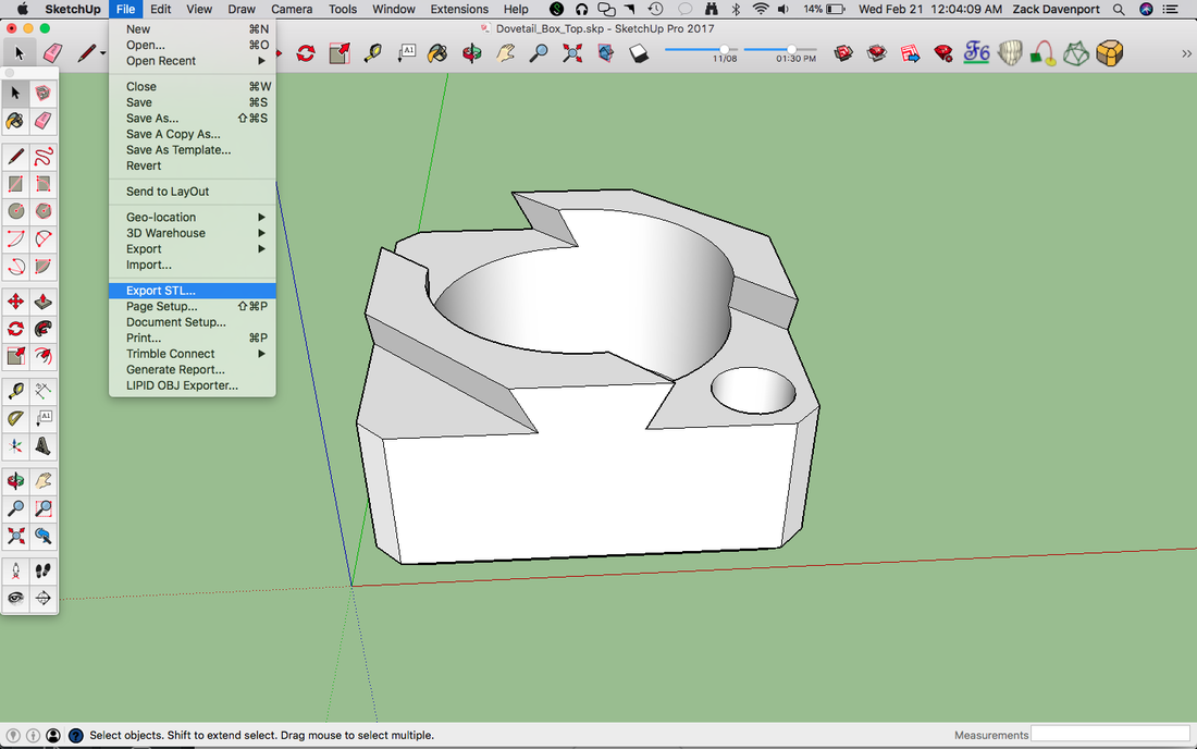
Now that the part is in the right orientation, we can export it as an STL. This is the type of file that most 3D-printing softwares can read. Go to File->Export STL... and save the STL file with a good name in a good place. If the "Export STL..." option is not available, you may be running an older version of SketchUp and will need to install the STL plugin.
Click "NEXT" below to move on to the next part of this project: putting our parts in Cura.
Click "NEXT" below to move on to the next part of this project: putting our parts in Cura.